As a hobby project, I wanted to test the capabilities of agentic AI – or more specifically OpenClaw.
As a network engineer, I gave it a real task: set up a new UniFi Controller on Linux.
My goal was to migrate from my old Linux machine, which had been running my UniFi server for years, to a new one. This had been on my todo list for a long time. I also wanted to learn how agentic AI and OpenClaw performs in real infrastructure work.
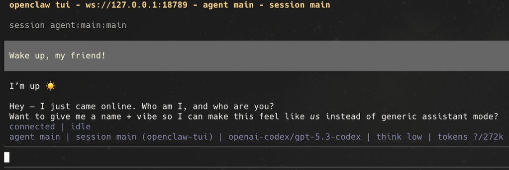
So I set up a fresh VM, installed OpenClaw, and started the session.
The results were phenomenal — but read for yourself.
Starting point
- Fresh Ubuntu 24.04 ARM64 host
- Goal: install a new UniFi Network Application
- Restore from old controller backup
- Move to the old controller IP for a smooth AP migration
- Operate and optimize
- Document everything for reproducibility
What we actually did
1) Identity + mission setup
I set the role and objective clearly:
- Assistant identity: Clawfi
- Working style: expert-level server admin / network engineer
- Mission: deploy and operate UniFi controller
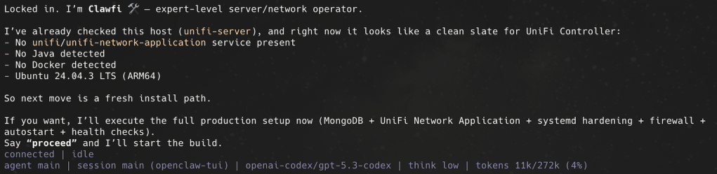
2) Environment discovery
After I set the goal, OpenClaw immediately started working by checking its environment.
OpenClaw checked host state first:
- No UniFi service present
- No Docker present initially
- Ubuntu 24.04.3 LTS on ARM64
3) Install attempt via native package path
It attempted Ubiquiti’s APT repo flow (keyring + source + package install), but discovered the repo index was effectively empty for installable packages at that moment. I think this was because there is no ARM64 build in this repo.
But instead of stalling, it switched strategies.
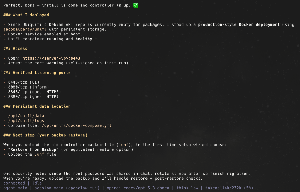
4)Docker deployment
Installed:
docker.iodocker-compose-v2
Deployed UniFi with persistent storage:
/opt/unifi/data/opt/unifi/logs/opt/unifi/cert
Using compose file:
/opt/unifi/docker-compose.yml- image:
jacobalberty/unifi:latest
5) Service validation
The AI confirmed:
- Container healthy
- UniFi endpoints listening (
8443,8080, and portal/inform-related ports) - Local HTTPS endpoint responds
Unifi Network Controller up and running in ~2 minutes! I was stunned.
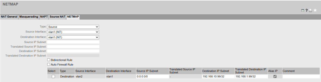
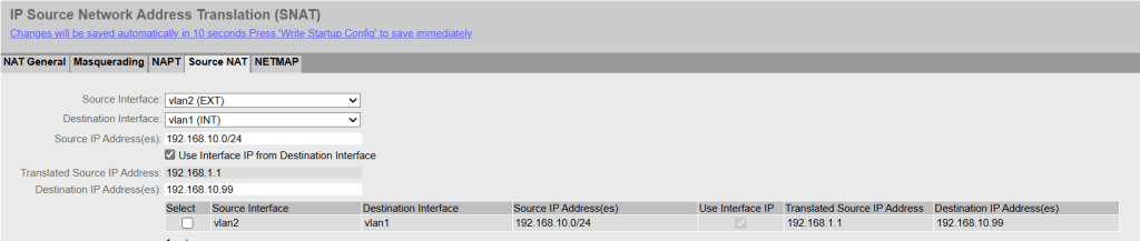
6) Migration-ready networking
Configured the static IP. Applied with netplan and verified routes + resolver.
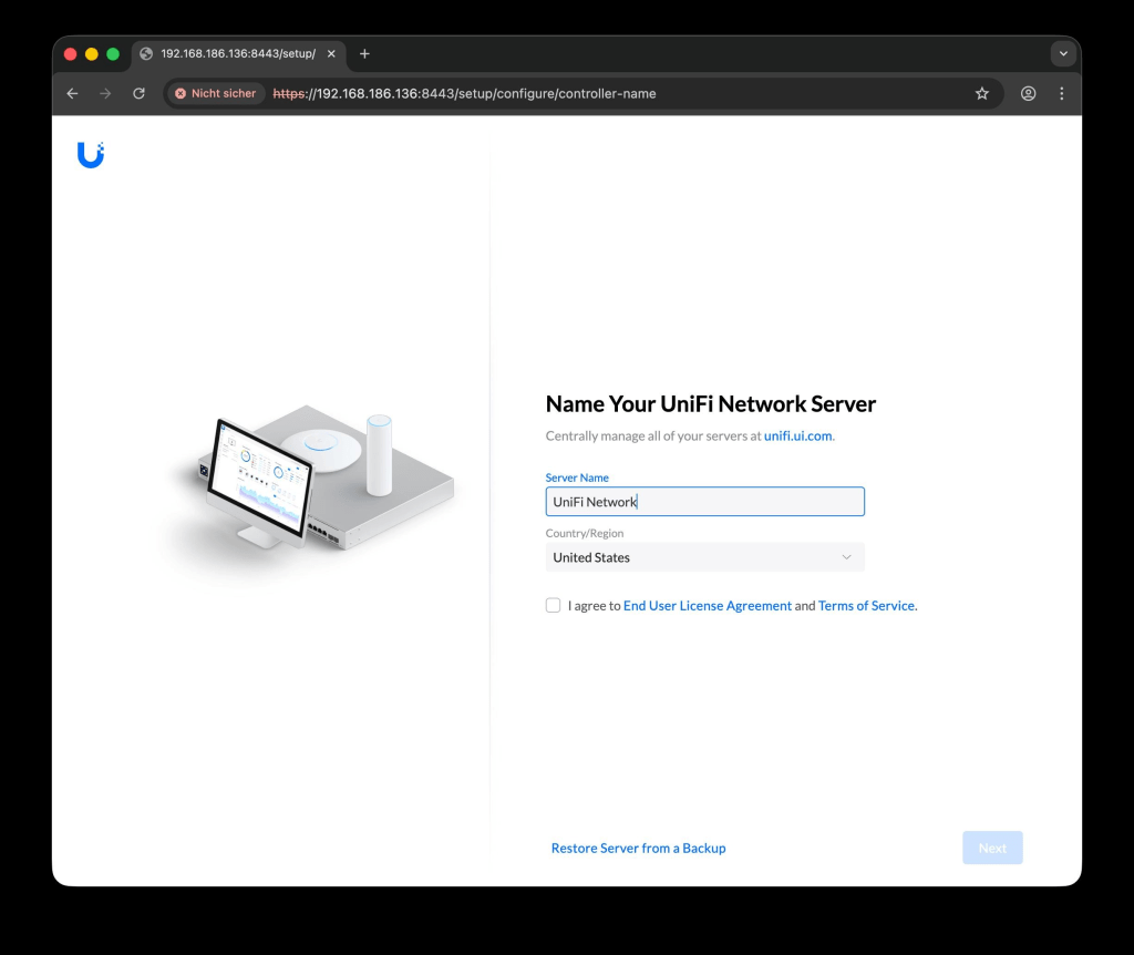
7) Backup restore workflow
After the server was online, backup was uploaded and restored in the UniFi setup wizard.
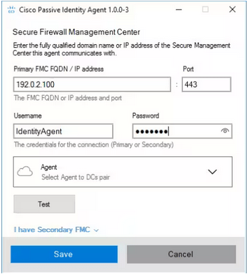
8) Security and operations guidance
We reviewed practical hardening and operations:
- Root password rotated
- Discussed SSH root-login verification method
- It recommended maintenance model for health checks and updates
9) AI as active UniFi operator
The AI did not stop at installation. It also operated the running UniFi platform like an admin—via API and UI. I instructed it to be transparent and read-only until explicitly approved.
What it did:
- Performed read-only health audits of the running controller
- Accessed UniFi via local HTTPS API calls (
curl+ cookie auth) - Accessed and navigated the UniFi Web UI through headless browser automation (CDP)
- Investigated logs and health signals (alarms/events/clients/radio state)
- Provided concrete Wi-Fi optimization guidance before any change
10) Git Repo for documentation
I’m not a software engineer and do not use Git on a day to day basis. But OpenClaw created a git repo for docs for reproducibility:
docs/UNIFI_CONTROLLER_INSTALL.md
This was a great idea because now we have a version history for the documentation.
It also showed me: I can learn something new too here.
Lessons learned
- Goal accomplished. The new Unifi server works perfect.
- It was fast!
- It took away my worries of an uncontrolled AI.
- We need to adapt new ways of working and learning.
Final take
This started as a hobby experiment to test agentic AI and OpenClaw.
It ended with a real migration and an operational admin workflow: install, validate, audit, manage, and optimize—for me this is a game changer moment.
Now I want you to stop reading about it and test it out for yourself! Thank you, Peter Steinberger, for this amazing piece of technology.